22+ Common emitter amplifier animation information
Home » Wallpapers » 22+ Common emitter amplifier animation informationYour Common emitter amplifier animation images are available in this site. Common emitter amplifier animation are a topic that is being searched for and liked by netizens now. You can Find and Download the Common emitter amplifier animation files here. Download all royalty-free vectors.
If you’re looking for common emitter amplifier animation pictures information connected with to the common emitter amplifier animation topic, you have pay a visit to the right site. Our site frequently provides you with suggestions for viewing the highest quality video and image content, please kindly search and locate more informative video content and images that match your interests.
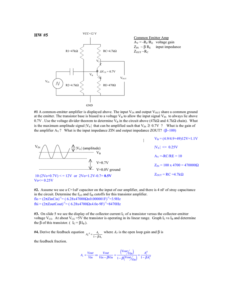
Common Emitter Amplifier Animation. The capacitor and the 110k and 10k resistors biasthe transistors base at about 17 V so that theaverage value of the input is moved up to that level. With and without Coupling Capacitor. Input is applied to the Base-Emitter terminal and output is taken from Emitter-Collector terminal. Common-emitter transistor amplifiers are so-called because the input and output voltage points share the emitter lead of the transistor in common with each other not considering any power supplies.
 Common Emitter Transistor Characteristics Youtube From youtube.com
Chapter 9 Common-Emitter Amplifiers Amplifier Gain The common-emitter CE amplifier provides voltage current and power gain. Input is applied to the Base-Emitter terminal and output is taken from Emitter-Collector terminal. This electronics video tutorial provides a basic introduction into the common emitter amplifier which uses a NPN bipolar junction transistor. Working of a pnp transistor is shown in above animation. They cannot directly handle voltages or currents that reverse direction. A simple animation of mine shows the operation of common emitter bjt amplifier using npn transistor.
The common-collector CC amplifier.
With and without Coupling Capacitor. A simple animation of mine shows the operation of common emitter bjt amplifier using npn transistor. This is a common-emitteramplifier which amplifies the input voltage about 10 times. The working model is explained for both the cases ie. If you have not been trained to work with high voltage then have an amp technician service your amp. The base-emitter junction is forward bias and emitter-collector junction is reverse bias it is because a transistor must remain in an active region in order to perform amplification.
 Source: itectec.com
This video explain bipolar junction transistor or bjt transistor in common emitter configuration as an amplifier with the help of animations. Working of a pnp transistor is shown in above animation. This video deals with the working of the common emitter amplifier. It offers high current gain medium input resistance and a high output resistance. In electronics a common-emitter amplifier is one of three basic single-stage bipolar-junction-transistor amplifier topologies typically used as a voltage amplifier.
 Source: youtube.com
Working of a pnp transistor is shown in above animation. Input is applied to the Base-Emitter terminal and output is taken from Emitter-Collector terminal. Common Emitter Amplifier has Emitter terminal as common for both input and output. The base-emitter junction acts likea diode so that the emitter will be a diode drop. A simple animation of mine shows the operation of common emitter bjt amplifier using npn transistor.
 Source: elprocus.com
The base-emitter junction is forward bias and emitter-collector junction is reverse bias it is because a transistor must remain in an active region in order to perform amplification. In electronics a common-emitter amplifier is one of three basic single-stage bipolar-junction-transistor amplifier topologies typically used as a voltage amplifier. Common Emitter Amplifier has Emitter terminal as common for both input and output. This electronics video tutorial provides a basic introduction into the common emitter amplifier which uses a NPN bipolar junction transistor. The output of a common emitter amplifier is 180 degrees out of phase to the input signal.
 Source: youtube.com
Shows the common emitter npn amplifier circuit. Voltage is known as bias voltage and its magnitude is such that it always keeps the emitter-base junction forward biased regardless of the polarity of the signal source. The base-emitter junction acts likea diode so that the emitter will be a diode drop. The Common Emitter Amplifier. This video explain bipolar junction transistor or bjt transistor in common emitter configuration as an amplifier with the help of animations.
 Source: youtube.com
The common-collector CC amplifier. The Common Emitter Amplifier - YouTube. With and without Coupling Capacitor. The base-emitter junction is forward bias and emitter-collector junction is reverse bias it is because a transistor must remain in an active region in order to perform amplification. In electronics a common-emitter amplifier is one of three basic single-stage bipolar-junction-transistor BJT amplifier topologies typically used as the v.
 Source: androiderode.com
In electronics a common-emitter amplifier is one of three basic single-stage bipolar-junction-transistor BJT amplifier topologies typically used as the v. Shows the common emitter npn amplifier circuit. They cannot directly handle voltages or currents that reverse direction. In electronics a common-emitter amplifier is one of three basic single-stage bipolar-junction-transistor BJT amplifier topologies typically used as the v. It offers high current gain medium input resistance and a high output resistance.
 Source: androiderode.com
The output of a common emitter amplifier is 180 degrees out of phase to the input signal. Transistors are essentially DC devices. Very easy understanding of common emitter bjt amplifierby java animation applet. The working model is explained for both the cases ie. The capacitor and the 110k and 10k resistors biasthe transistors base at about 17 V so that theaverage value of the input is moved up to that level.
 Source: pt.slideshare.net
Source: pt.slideshare.net
This video explain bipolar junction transistor or bjt transistor in common emitter configuration as an amplifier with the help of animations. Voltage is known as bias voltage and its magnitude is such that it always keeps the emitter-base junction forward biased regardless of the polarity of the signal source. Transistors are essentially DC devices. Very easy understanding of common emitter bjt amplifierby java animation applet. This video deals with the working of the common emitter amplifier.
 Source: youtube.com
The output of a common emitter amplifier is 180 degrees out of phase to the input signal. If playback doesnt begin shortly try restarting your device. The working model is explained for both the cases ie. Common Emitter Amplifier - YouTube. A simple animation of mine shows the operation of common emitter bjt amplifier using npn transistor.
 Source: youtube.com
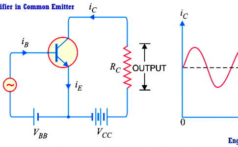
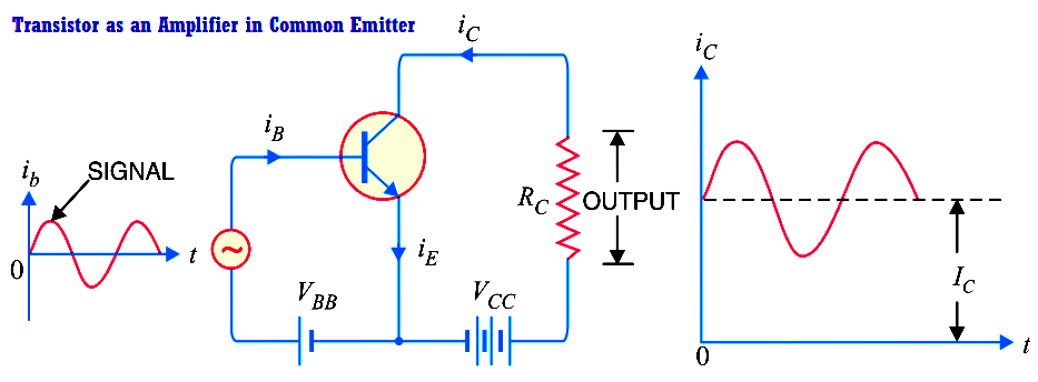
With and without Coupling Capacitor. Input is applied to the Base-Emitter terminal and output is taken from Emitter-Collector terminal. The capacitor and the 110k and 10k resistors biasthe transistors base at about 17 V so that theaverage value of the input is moved up to that level. The common-collector CC amplifier. Note that a battery V BB is connected in the input circuit in addition to the signal voltage.
 Source: indiabix.com
Very easy understanding of common emitter bjt amplifierby java animation applet. Input is applied to the Base-Emitter terminal and output is taken from Emitter-Collector terminal. Voltage is known as bias voltage and its magnitude is such that it always keeps the emitter-base junction forward biased regardless of the polarity of the signal source. Note that a battery V BB is connected in the input circuit in addition to the signal voltage. This video explain bipolar junction transistor or bjt transistor in common emitter configuration as an amplifier with the help of animations.
 Source: pinterest.com
They cannot directly handle voltages or currents that reverse direction. Very easy understanding of common emitter bjt amplifierby java animation applet. Common Emitter Amplifier has Emitter terminal as common for both input and output. If you have not been trained to work with high voltage then have an amp technician service your amp. The capacitor and the 110k and 10k resistors biasthe transistors base at about 17 V so that theaverage value of the input is moved up to that level.
 Source: studylib.net
The base-emitter junction acts likea diode so that the emitter will be a diode drop. They cannot directly handle voltages or currents that reverse direction. It offers high current gain medium input resistance and a high output resistance. If you have not been trained to work with high voltage then have an amp technician service your amp. This video deals with the working of the common emitter amplifier.
 Source: engineeringtutorial.com
A simple animation of mine shows the operation of common emitter bjt amplifier using npn transistor. Chapter 9 Common-Emitter Amplifiers Amplifier Gain The common-emitter CE amplifier provides voltage current and power gain. The base-emitter junction is forward bias and emitter-collector junction is reverse bias it is because a transistor must remain in an active region in order to perform amplification. This electronics video tutorial provides a basic introduction into the common emitter amplifier which uses a NPN bipolar junction transistor. A simple animation of mine shows the operation of common emitter bjt amplifier using npn transistor.
 Source: youtube.com
Shows the common emitter npn amplifier circuit. Note that a battery V BB is connected in the input circuit in addition to the signal voltage. Chapter 9 Common-Emitter Amplifiers Amplifier Gain The common-emitter CE amplifier provides voltage current and power gain. Working of a pnp transistor is shown in above animation. Transistors are essentially DC devices.
 Source: instrumentationtools.com
Note that a battery V BB is connected in the input circuit in addition to the signal voltage. In electronics a common-emitter amplifier is one of three basic single-stage bipolar-junction-transistor amplifier topologies typically used as a voltage amplifier. The Common Emitter Amplifier - YouTube. The base-emitter junction acts likea diode so that the emitter will be a diode drop. Shows the common emitter npn amplifier circuit.
 Source: electrical4u.com
Note that a battery V BB is connected in the input circuit in addition to the signal voltage. Easily understanding of common emitter amplifier. Note that a battery V BB is connected in the input circuit in addition to the signal voltage. Transistors are essentially DC devices. The capacitor and the 110k and 10k resistors biasthe transistors base at about 17 V so that theaverage value of the input is moved up to that level.
 Source: youtube.com
The working model is explained for both the cases ie. Common Emitter Amplifier - YouTube. Working of a pnp transistor is shown in above animation. In this circuit the base terminal of the transistor serves as the input the collector is the output. Transistors are essentially DC devices.
This site is an open community for users to do submittion their favorite wallpapers on the internet, all images or pictures in this website are for personal wallpaper use only, it is stricly prohibited to use this wallpaper for commercial purposes, if you are the author and find this image is shared without your permission, please kindly raise a DMCA report to Us.
If you find this site good, please support us by sharing this posts to your favorite social media accounts like Facebook, Instagram and so on or you can also save this blog page with the title common emitter amplifier animation by using Ctrl + D for devices a laptop with a Windows operating system or Command + D for laptops with an Apple operating system. If you use a smartphone, you can also use the drawer menu of the browser you are using. Whether it’s a Windows, Mac, iOS or Android operating system, you will still be able to bookmark this website.
Category
Related By Category
- 27+ Anime eyes female information
- 48++ Classification of marine animals ideas
- 31++ Apple animation company ideas
- 29+ Extinct animals seen again information
- 41++ Best animation k 3d information
- 34++ Animal testing pressure groups ideas
- 38++ Animation jobs in usa ideas in 2021
- 37++ Animated drop of water information
- 50+ Dangerous wild animals attack videos ideas in 2021
- 42+ Bacteria animated gif ideas